SparkFun MicroMod Main Board - Double

SparkfunSKU: DEV-20595
Price:
Sale price £17 Regular price £20
incl. VAT
excl. VAT
Save 15%
Stock:
Only 4 units left
Quantity:

Awesome Extras

SparkfunSparkFun MicroMod RP2040 Processor
Sale price £15.60 incl. VAT excl. VAT
The Pi HutUSB-A to USB-C Cable - Black
Sale priceFrom £2.25 incl. VAT excl. VAT

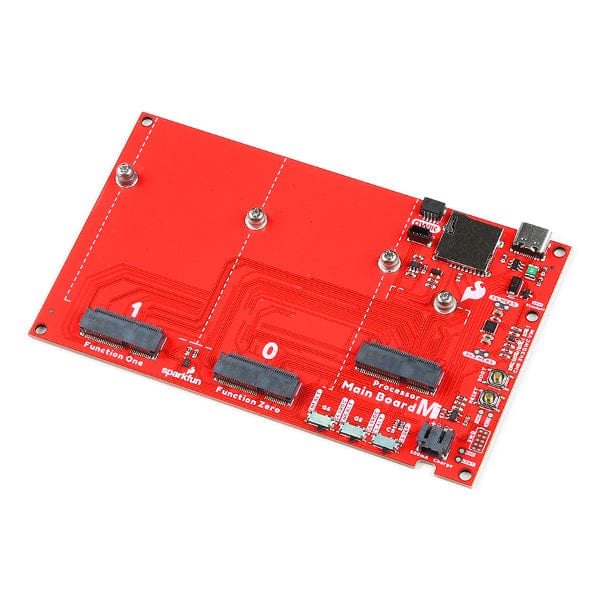
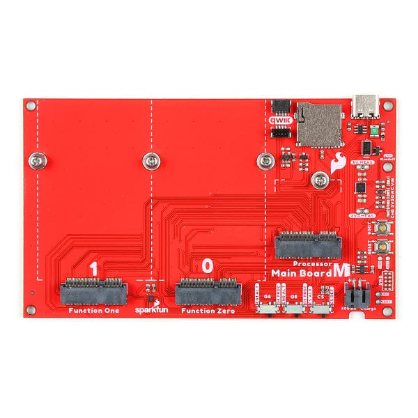
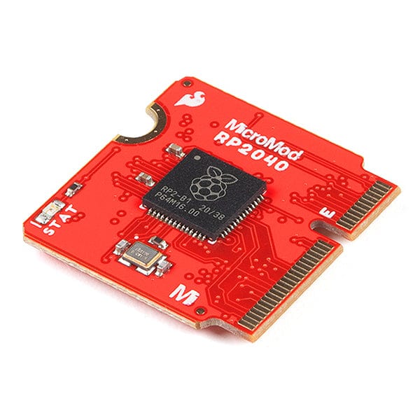
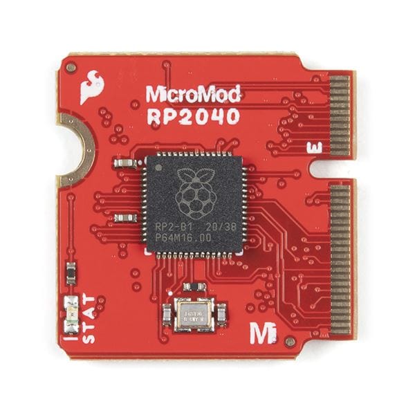
The MicroMod Main Board - Double is a specialized carrier board that allows you to interface a MicroMod Processor Board with up to two MicroMod Function Boards. With the M.2 MicroMod connector, connecting your Processor and Function Boards is a breeze. Simply match up the key on your board's bevelled edge connector to the key on the M.2 connector and secure the boards with screws.

The Double Main Board includes one USB-C connector for power and programming the Processor Board. A jumper is available on the back of the board to isolate the USB C's shield pin. Two buttons for reset and boot are also populated on the board. Processor Board pins are also broken out as 2x5 SWD pins. Also, included on the board is a 2A resettable fuse and 3.3V/1A voltage regulator. A second 3.3V/500mA voltage regulator is included on the board to power your Qwiic-enabled devices. We've even added convenient PTH jumpers for advanced users looking to bypass the fuse and measure the current consumption on the 5V and 3.3V lines for low-power testing. For those that need to go remote with their application, the board includes a 2-pin JST connector and a single-cell LiPo MCP73831 charge IC (set to a charge rate of 500mA).

Two switches have been included to toggle between the general-purpose pins and each Function Board's voltage regulator. A third switch has also been included to switch between different SPI chip select pins on the second Function Board. Four status LEDs are available for power and charging. These can also be disabled through the jumpers. There is a microSD card socket so you can also plug in a microSD card for data logging. The microSD socket can be disabled through the I/O pins. Finally, two Qwiic connectors are populated on the board with built-in pull-up resistors to easily add Qwiic-enabled I2C devices to your projects!

Note: A MicroMod Processor and Function Boards are not included with the MicroMod Main Board. These boards will need to be purchased separately.

Get started with the Micromod Main Board Guide V2

Features

  • Input Voltage Range
    • 5V via USB C Connector
    • ~3.7V to 4.2V via LiPo Battery Connector
  • Built-in Resettable PTC Fuse (Rated 5V/2A)
  • AP7361C 3.3V Voltage Regulator (Rated 1A)
  • AP7347DQ 3.3V Voltage Regulator (Rated 500mA)
  • Integrated MCP73831 Single Cell LiPo Charge Circuit
    • 500mA
  • Ports
    • 1x USB Type C Connector
    • 1x 2-Pin JST Connector
    • M.2 Connectors
      • 1x MicroMod Processor Board
      • 2x MicroMod Function Boards
    • 2x Qwiic Enabled I2C
    • 1x MicroSD Card Socket
    • 1x SWD 2x5 Header
  • Built-in MUX for UART1
  • Buttons
    • 1x Reset
    • 1x Boot
  • 3x Switches
    • Function Board Zero Power Enable Pins
    • Function Board One Power Enable Pins
    • SPI1 Chip Select Alternative Pins
  • LEDs
    • 1x VIN
    • 1x 3.3V
    • 1x Qwiic 3.3V
    • 1x CHG
  • Plated Through Holes
    • RST
    • 5V (MEAS)
    • V_BATT
    • 3.3V (MEAS)
  • Jumpers
    • USB SHLD
    • 5V MEAS
    • 3.3V MEAS
    • PTC
    • 3.3V EN
    • VIN LED
    • 3.3V LED
    • Qwiic 3.3V LED
    • I2C
    • Battery Voltage Divider
  • Board Dimensions
    • 4.90" x 2.90"

Revision Changes: The following changes for v22 include:

  • Rotate the silkscreen for the connectors and a majority of the labels.
  • Add TVS diodes for ESD protection on the USB pins.
  • Add SHLD jumper to isolate the USB Type C connector's shield pin.
  • Add a 5V MEAS PTH jumper as a measurement for 5V.
  • Remove the 500mA/100mA selector for the LiPo charge circuit. The board now charges at a default rate of 500mA only.
  • Add a DIVIDER jumper to remove the resistor divider that is connected to the processor's "BATT_VIN/3" pin for low-power applications.
  • Add a dedicated 3.3V/500mA voltage regulator for the Qwiic port.
  • Add GPIO control of 3.3V voltage regulator (I2C_SCL1-Processor).
  • Add a LED for the 3.3V Qwiic port with a QWIIC LED jumper to disable.
  • Add a transistor to disable power to the microSD socket (can be controlled using I2C_SCL1-Processor).
  • Add multiplexed primary UART pins to send serial data to Function Board(s).
  • Add two 2.2kΩ I2C pull-ups to the primary I2C pins with jumpers (I2C) to disable.
  • Replace male header pins and 2-pin shunt with SMD switches to adjust the Function Board Power enable pins.
  • Add an option to adjust Function Board One's secondary SPI CS pin (i.e. "CS1-processor" and "A1-processor") with an SMD switch.

Resources

Package Contents

  • 1x MicroMod Main Board - Double
  • 4x Phillips #0 M2.5x3mm Screws

Payment & Accreditations

Payment methods
Visa Mastercard Maestro PayPal Amazon Klarna

Your payment information is processed securely. We do not store credit card details nor have access to your credit card information.

Accreditations