 Skip to content
Coding Colour with MicroPython on Raspberry Pi Pico Displays
Got a Waveshare Raspberry Pi Pico LCD display but not sure where to start? How about experimenting with colours and shapes with MicroPython!
In this article we will show you colour control using MicroPython with Waveshare Raspberry Pi Pico displays, including:
- How screen colours are controlled
- Basic text and graphical drawing instructions - rectangles
- How to input values from potentiometers within a given range
- How to build a simple colour mixing application with additional components
What you’ll need
- Raspberry Pi Pico (with male pins soldered)
- Thonny installed on your computer
- A Micro-USB cable – for power and programming the Pico
- Ability to enter, edit, save and execute MicroPython code on your Pico using Thonny
- A Waveshare Pico LCD Display – see options below
- Optional:
Display Options
We sell several bright and colourful Pico displays from Waveshare with different sizes, pixel counts and features. In order of size:
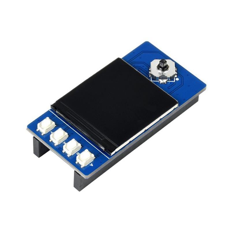
- 0.96” 160x80 pixels, with joystick and 2 buttons
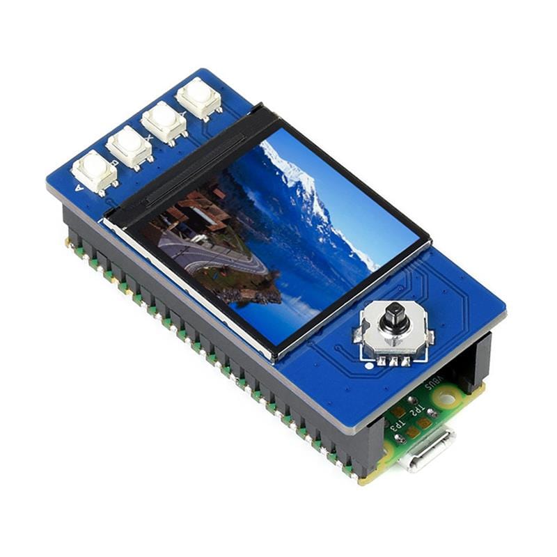
- 1.3” 240x240 pixels, with joystick and 4 buttons
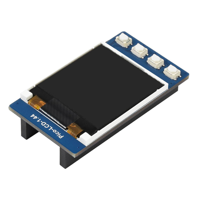
- 1.44” 128x128 pixels with 4 buttons
- 1.8” 160x128 pixels
- 2.0” 320x240 pixels with 4 buttons
These displays all plug directly into the pins of your Pico and are programmed in the same way but require slightly different driver code, supplied by Waveshare via their Wiki pages.
Comparing the displays
All these displays need some memory in the Pico, a 'buffer', to hold the data to be displayed on the screen. As the number of pixels increases so does the size of this buffer requirement and the space available for code decreases. As the pixel size gets smaller the basic text gets progressively harder the read as it is so small.|
Size |
0.96" | 1.3" | 1.44" | 1.8" | 2.0" |
| Pixels | 160x80 | 240x240 | 128x128 | 160x128 | 320x240 |
| Buffer | 25600 | 115200 | 32768 | 40960 | 153600 |
| Driver | ST7735S | ST7789 | ST7735S | ST7735S | ST7789VW |
| Joystick | Y | Y | N | N | N |
| Buttons | 2 | 4 | 4 | 0 | 4 |
| GPIO used | 13 | 15 | 10 | 6 | 10 |
For this tutorial we are going to use the 1.44” 128x128 display as it provides a good compromise between basic text size, number of pixels on the display for graphics, buffer size, input buttons and price. The code is easily converted to run on the other displays.
Hardware Connection
This is simple – just push the Pico’s pins into the socket on the rear of the display and use the USB cable to connect it to your computer. Make sure you have it the right way round - the USB end is marked on the bottom of the board. Once Thonny has been installed we are ready to go.
As usual, Waveshare provide a basic example MicroPython program with the driver included. You can find the documentation and code here.
The file needs to be unzipped. The code is quite long because it contains the complicated driver for the board, but we do not need to understand how it works to make full use of it.
The co-ordinate system
With the buttons on the right and the USB cable on the left, the top left corner is the origin with x = 0 and y = 0 (0, 0)
This screen has a width and height of 128 pixels so the bottom right corner will be (127, 127). The pixels are counted 0 to 127 inclusive.
The most useful section is here:
LCD = LCD_1inch44()
#color BRG
LCD.fill(LCD.BLACK)

LCD.show()

LCD.fill_rect(15,40,75,12,LCD.YELLOW)
LCD.rect(15,40,75,12,LCD.YELLOW)
LCD.text("1in44-LCD",17,42,LCD.WHITE)
The next instruction fills the display buffer with the number representing BLACK (at this point the display does not change):
LCD.fill(LCD.BLACK)LCD.show()LCD.show()LCD.fill_rect(15,40,75,12,LCD.YELLOW)LCD.rect(15,40,75,12,LCD.YELLOW)LCD.text("1in44-LCD",17,42,LCD.WHITE)Investigating the colour coding system
All of these Waveshare displays use 16-bit colour codes to mix colours by varying the brightness ratios of red, green and blue in each pixel. As human eyes are more sensitive to green light, an extra bit is given to the green component. This code is called RGB565 with 5 bits for red and blue and 6 bits for green.
5-bits provide 32 different levels of brightness, 0 to 31, and 6-bits allow 64 levels, 0 to 63. By mixing these together we can generate 32 x 64 x 32 = 65536 different colours!
Red and Blue brightness levels will be: OFF, or a combination of 1, 2, 4, 8 and 16. Green will be OFF, or a combination of 1, 2, 4, 8, 16 and 32.
Each of these coloured-brightness levels is switched on or off by a single bit in a 2 byte, 16-bit number. If more than one is switched on at the same time the brightness adds up. If all are switched off the screen shows black. If all are switched on the screen shows white.
We need to know which colour, and how bright each of the 16 bits of the colour control values, contribute to the final colour.
This code helps find the answer:
bits = []
bit = 1
for i in range(16):
    bits.append(bit)
    bit = bit *2
print(bits)
hexx = "0123456789ABCDEF" # Bit count in base 16 – Hexadecimal – as a string.
clear(0)
lcd.text("Colour",25,5,colour(255,0,0))         # RED Screen heading
lcd.text("Control",25,15,colour(0,200,0))       # GREEN
lcd.text("Bits 0-15",25,25,colour(0,0,255))     # BLUE
for i in range(16):
    bit = 15 - i
    lcd.fill_rect(i*8,40,8,90,bits[bit])  # Coloured rectangle
    lcd.text(hexx[bit],i*8,50+i*4,colour(150,150,150)) # Hex symbol

lcd.show()   # Makes the instructions visible on the screen
utime.sleep(7) # Delay for 7 seconds
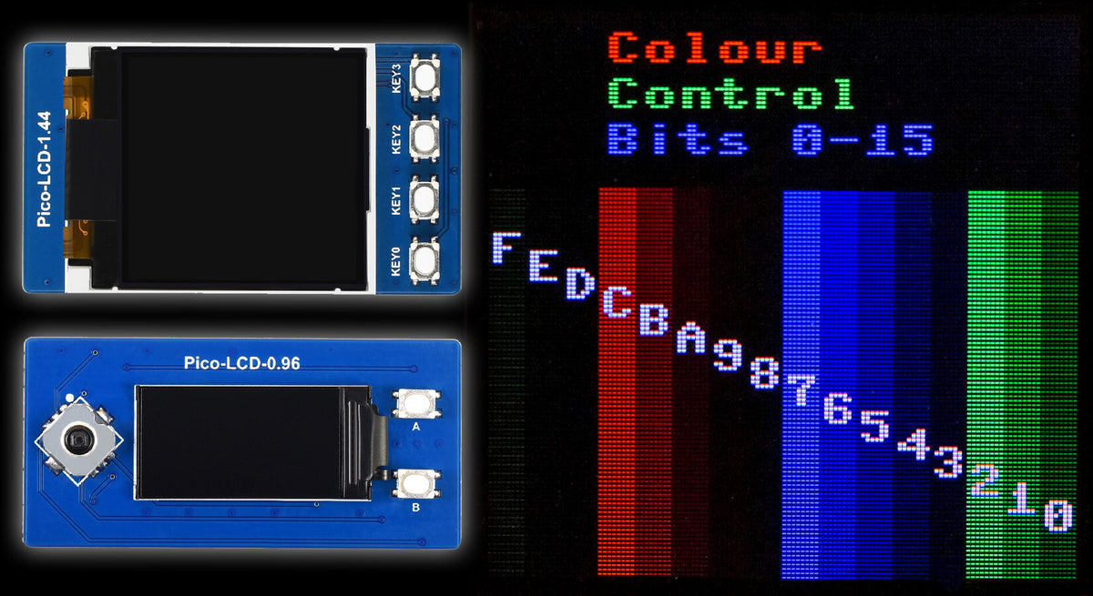
Executing this code produces the following image:

Probably not what you expected!
Blue is controlled by bits 3,4,5,6 and 7
Red is controlled by bits 8,9,10,11 and 12
Green is controlled by bits 13,14,15,0,1 and 2
In each case listing dimmest to brightest. You can even see the individual pixels. To get the brightest rendering of each colour all its control bits have to be turned on together:
- 11100000 00000111 is brightest green
- 00011111 00000000 is brightest red
- 00000000 11111000 is brightest blue
- 00000000 00000000 is black = 0x0000
- 11111111 11111111 is brightest white => red, green and blue all full on => 0xFFFF
Making it simpler with RGB!
These binary patterns are difficult to understand. So, we have written a function to produce any of the available colours from a much simpler system. You can use:
code = colour(r, g, b)
where r, g and b represent the brightness of the three basic colours in the range 0 to 255. For example:
- red = colour(255, 0, 0) is bright red
- green = colour(0, 255, 0) is bright green
- blue = colour(0, 0, 127) is half-power blue
- yellow = colour(255, 255, 0) Red + Green
- cyan = colour(0, 255, 255) Green + Blue
- magenta = colour(255, 0, 255) Red + Blue
- white = colour(255, 255 ,255) Red + Green + Blue
- mid-grey = (127, 127, 127) Half brightness of white
(If you have used addressable RGB LEDS you will be familiar with this RGB888 format to define a colour.)
Here is the function:
def colour(R,G,B): # Convert RGB888 to RGB565
    return (((G&0b00011100)<<3) +((R&0b11111000)>>3)<<8) + (B&0b11111000)+((G&0b11100000)>>5)
This involves bit-masks and bit shifting. You do not need to understand how it works to use it but this may help if you want to understand what is going on:
7 6 5 4 3 2 1 0 7 6 5 4 3 2 1 0 7 6 5 4 3 2 1 0 (RGB888 = 24-bit -> 3 separate bytes).
These bits are transformed into this:
4 3 2 7 6 5 4 3 7 6 5 4 3 7 6 5 (RGB565 = 16-bit -> 2 bytes holding a 16-bit number)
Here's an explanation to make it clearer (if you're curious!):
Least significant byte
((G&0b11100000)>>5) Select the top 3 green bits and shift 5 places right -> 00000111
(B&0b11111000) Select all the blue bits -> 11111000
Most significant byte
((G&0b00011100)<<3) Select the lowest 3 green bits and shift 3 places left ->1110000
((R&0b11111000)>>3) Select all the red bits and shift 3 places right -> 00011111
<<8 Shift whole byte left 8 places => more significant byte
The end result is: 11111111 11111111
Download the Programs
You can download the 5 Colour Check programs here:
- WS 0-96 160x80 Colour Check.py
- WS 1-3 240x240 Colour Check.py
- WS 1-44 128x128 Colour Check.py
- WS 1-8 160x128 Colour Check.py
- WS 2-0 320x240 Colour Check.py
Demonstrated Procedures
This procedure clears the screen to the given colour:
def clear(c):
    lcd.fill(c)

clear(0) # Black background
lcd.show()

clear(colour(160, 160, 160)) # Grey background
lcd.show()
srs =["Green 4","Green 5","Green 6","Blue 0","Blue 1","Blue 2","Blue 3","Blue 4","Red 0","Red 1","Red 2","Red 3","Red 4","Green 0","Green 1","Green 2"]
for i in range(16):
    lcd.fill(bits[i])
    lcd.text("Bit "+str(i),20,20,colour(200,200,200))
    lcd.text(srs[i],20,35,colour(200,200,200))
    lcd.show()
utime.sleep(1.5)clear(0)
lcd.text("Red",0,0,colour(255,0,0))
lcd.text("Green",0,10,colour(0,255,0))
lcd.text("Blue",0,20,colour(0,0,255))
lcd.text("Yellow",0,30,colour(255,255,0))
lcd.text("Cyan",0,40,colour(0,255,255))
lcd.text("Magenta",0,50,colour(255,0,255))
lcd.text("Dark Orange",0,60,colour(255,165,0))
gc.collect()
lcd.text("Mem free: "+str(gc.mem_free()),0,70,0xFFFF)
lcd.show()
utime.sleep(6)pwm.duty_u16(32768)#max 65535 ========= HALF BRIGHTNESS
clear(0)
lcd.show()Note: The colour constants given in the 1.44” driver are not all correct. That is why the YELLOW background appears to look pink. We suggest you use the colour(R, G, B) function.
At this point we ported the code to work on the other four displays and found that they use a slightly different system - the blue and red bits have been swapped over:

For these boards we need to change the colour function to:
def colour(R,G,B): # Convert RGB888 to RGB565
return (((G&0b00011100)<<3) +((B&0b11111000)>>3)<<8) + (R&0b11111000)+((G&0b11100000)>>5)
Just exchange the R and B variable positions.
Easy-Start Downloadable Setup Programs
To make things easy we are providing minimum setup programs for each of the 5 boards. Each program includes the correct screen driver, sets up the buttons and joystick, if available, and includes the correct version of the colour(R, G ,B) function. It also displays a 3-line colour check at the start.
You can download the basic program to drive your board here:
- WS 0-96 160x80 MIN.py
- WS 1-3 240x240 MIN.py
- WS 1-8 160x128 New Driver MIN.py
- WS 1-44 128x128 MIN.py
- WS 2-0 320x240 MIN.py
Each program contains the screen driver code, sets up the buttons/joystick and sets the width and height variables correctly, loads the essential libraries, defines the colour(R, G, B) and clear(c) procedures. It then displays some colour checking text.
We suggest that you save the one for your board and use it as a starting point for developing new projects.
Things to try
1. Draw 50 randomly sized rectangles in random colours on the screen. Hint: Here's how to generate random numbers:
import random
for i in range(10):
print(random.randint(0,255)) #numbers in range 0 - 255
2. Near the centre of the screen, on a dark grey background, display your name, in red, and post/zip code, in cyan. Indent the post code by 10 pixels more than your name.
3. Centre both the name and post code on their lines.
Colour mixing project
At this point we need to separate the Pico and the display. We need access to some of the GPIO pins to attach three 10 K 0hm potentiometers. You could press the Pico into a breadboard or, more conveniently use a Pico Decker, which has all the Pico pins neatly numbered and named. The circuit is shown in the diagram.

If your display has buttons, you will not need the extra one here. Connect up the SPI, power and button pins from your display (the product page/Wiki page for your particular display will show the pinout).
Connections to the breadboard circuit
- Black to GND
- Orange to 3.3V
- Red to ADC0 = GP26
- Green to ADC1 = GP27
- Blue to ADC2 = GP28
- Yellow to GP15 = Key0 on the 1.44” display
In Thonny make a new copy of the Colour Check program for your display.
(File => Save as One Pot.py)
In the copy, delete the code below the # ========== END OF SETUP === MAIN =========== line.
Copy the following code and paste it onto the end of the program:
# Set up potentiometers
rpot=machine.ADC(26)
gpot=machine.ADC(27)
bpot=machine.ADC(28)
c = colour(0,0,0) # BLACK
for i in range(100):
r = rpot.read_u16()
print(r)
clear(r)
lcd.text(str(r),10,10,c)
lcd.text(str(hex(r)),10,20,c)
lcd.show()
utime.sleep(0.5)
pwm.duty_u16(32768)#max 65535 ========= HALF BRIGHTNESS
clear(0)
lcd.show()
Turn the turn the RED potentiometer, on GP26. You should see rapid colour changes on the screen and changes in the bottom window of Thonny – Shell area. The numbers should range from zero to 65535 – the full 16-bit range used for our colour codes. We usually get the top value, or very near it, but have never managed to get the zero.
For this project we need to obtain values from 0 to 255 to represent the three primary colours – red, green and blue. We will need to make some adjustments with the software!
Change to loop counter to 10. Turn the potentiometer to its low end and run the program again.
We got this:
>>> %Run -c $EDITOR_CONTENT
272
320
288
272
288
304
320
304
272
288
So, we changed the loop to:
t = 0
for i in range(10):
    r = rpot.read_u16()
    print(r)
    t = t + r
    utime.sleep(0.1)
print("Average: ",int(t/10))
Which then gave us:
288
320
320
336
304
288
352
288
720
272
Average: 348
Changing the pot reading line to:
r = int((rpot.read_u16() - 348) /255)
for i in range(10):
    r = int((rpot.read_u16() - 348) /255)
    if r < 0:
        r = 0
    print(r)
    utime.sleep(0.1)
Now we can get accurate input values we can produce a colour mixing program. We need four rectangles. The three smaller rectangles show the setting for red, green and blue. The last, a larger rectangle shows the colour made by combining them.
Save the current program as Pots Mixing.py and replace the loop with:
for i in range(100):
    r = int((rpot.read_u16() - 348) /255)
    if r < 0:
        r = 0
    g = int((gpot.read_u16() - 348) /255)
    if g < 0:
        g = 0
    b = int((bpot.read_u16() - 348) /255)
    if b < 0:
        b = 0
    print(r, g, b)
    utime.sleep(0.5)
Turn all three pots in turn and check that the range of each is 0 – 255. The 1.44” display is 128 x 128 so we added these lines just above the loop and updated the loop.
width = 128   # Display size in pixels
height = 128  # Adjust for your display

w3 = int(width / 3)
h2 = int(height / 2)

while True:
    r = int((rpot.read_u16() - 348) /255)
    if r < 0:
        r = 0
    g = int((gpot.read_u16() - 348) /255)
    if g < 0:
        g = 0
    b = int((bpot.read_u16() - 348) /255)
    if b < 0:
        b = 0
    print(r, g, b)

    lcd.fill_rect(0,0,w3,h2,colour(r,0,0)) # RED
    lcd.fill_rect(w3+1,0,w3,h2,colour(0,g,0)) # GREEN
    lcd.fill_rect(w3*2+2,0,w3,h2,colour(0,0,b)) # BLUE
    lcd.fill_rect(0,h2,width,h2,colour(r,g,b)) # MIXED

    c = colour(255,255,255)
    lcd.text(str(r),10,10,c)
    if g > 200:
        c = 0
    lcd.text(str(g),10+w3,10,c)
    c = colour(255,255,255)
    lcd.text(str(b),10+w3*2,10,c)
    c = colour(255,255,255)
    if r+g+b > 300:
        c = 0
    lcd.text(str(colour(r,g,b)),10,10+h2,c)
    lcd.text(str(hex(colour(r,g,b))),10 + int(width/2),10+h2,c)
    lcd.show()
    utime.sleep(0.5)
How it works
- Calculate values for a third of the width and half the height
- Read the three pots and adjust the range to 0 – 255
- Draw the four rectangles: Red, Green, Blue and Mixed
- Write numeric values in the rectangles in a contrasting colour
Running the program and turning the pots allows the user to mix any of the available 65 K colours and read off the colour value.
You can download the finished code here: WS 1-44 128x128 Pots Mixing.py
Things to try
- Try turning the pots to find the colour codes for: Bright Orange, Bright Pink, Dark Brown, Light Brown, Violet, Light Yellow, Lime Green. ( https://htmlcolors.com/ might help if you are stuck.)
- Add the hex value in the 3 small rectangles
- Stop the loop by pressing the button; then tidy up
- Make the rectangles slightly smaller showing more black background Draw Red, Green, Blue and White frames round the rectangles
- Add a Title screen at the start, with instructions.
We hope you have found this tutorial useful and interesting!
About the Author
This article was written by Tony Goodhew. Tony is a retired teacher of computing who starting writing code back in 1968 when it was called programming - he started with FORTRAN IV on an IBM 1130! An active Raspberry Pi community member, his main interests now are coding in MicroPython, travelling and photography.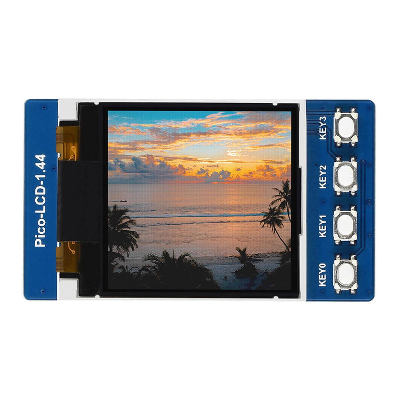
3 comments
Alan
All these Waveshare LCD panels and their drivers framebuffers are actually RGB666 with 262K colours. It’s the example libraries which are limited to using RGB565 with 64K colours – which is then converted by the driver using a lookup table to the final RGB666 – for simplicity and balance between colour reproduction and memory saving (if you use a scratch framebuffer in Pico’s memory as the example libraries mostly do).
When programmed, you can change on the fly between RGB565, RGB666 or RGB444 for uploading image data . For my use I draw nicer static RGB666 images directly from flash, using __in_flash() in C code, to the drivers framebuffer saving on Picos limited memory.
Jose
Any idea of how to display a picture?
Any idea of how to display a picture?
Jose
Thank you so much for this tutorial. It clarify many questions that I had.
Thank you so much for this tutorial. It clarify many questions that I had.